Tel: +1 (832) 555-0147 Email: [email protected]

Howden AeroFlow Fan Engineering & Aerodynamic Technology

Computational fluid dynamics, AMCA-certified testing, and two decades of impeller optimization converge in every fan we build.

CFD simulation of centrifugal fan airflow

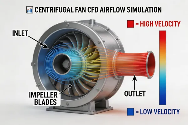
Computational Fluid Dynamics

Every Howden AeroFlow impeller begins as a parametric CFD model. Our 62-person engineering team runs steady-state and transient simulations across the full operating envelope — from surge to stall — mapping pressure distributions, velocity profiles, and turbulence intensity before a single blade is cast.

This simulation-first approach reduces physical prototyping cycles by 60% and allows us to optimize blade profiles for specific applications: high-temperature power plant flue gas, abrasive cement kiln exhaust, or low-noise data center cooling.

  • Full 3D RANS and LES turbulence modeling
  • Multi-point optimization across 5+ operating conditions
  • Aero-acoustic modeling for noise prediction within ±2 dB(A)
AMCA certified fan testing facility

AMCA-Certified Performance Testing

Our test facilities comply with AMCA Standard 210 (Laboratory Methods of Testing Fans for Certified Aerodynamic Performance Rating). Every production fan series undergoes witnessed performance testing to validate air volume, static pressure, brake horsepower, and efficiency at rated conditions.

Test data is delivered with certified fan curves showing actual performance versus predicted curves, giving specifying engineers confidence that the installed fan will meet their system requirements.

  • AMCA 210 / ISO 5801 compliant test chambers
  • Sound testing per AMCA 300 / ISO 13347
  • Certified fan curve data package included with every order
VFD control system for industrial fans

Variable Frequency Drive Integration

All Howden AeroFlow fan series are engineered for VFD operation across the full speed range from 15 Hz to 60 Hz. Motor windings are insulated to NEMA MG1 Part 31 / IEC 60034-18-42 standards to withstand inverter-induced voltage spikes.

Our application engineers model system resistance curves against fan performance at multiple speeds to determine the optimal VFD control strategy — constant volume, constant pressure, or sensorless vector — maximizing energy savings while protecting bearings and structural integrity.

  • 25-45% energy savings at part-load operation
  • Bearing life analysis for variable-speed duty
  • Harmonic distortion mitigation (IEEE 519 compliance)
Fan impeller manufacturing

Materials & Protective Coatings

Fan components operating in corrosive or abrasive gas streams demand material specifications beyond standard mild steel. Our metallurgical engineers select from Corten A, 316L stainless, Inconel, and Hastelloy alloys matched to the specific flue gas chemistry and temperature.

Surface treatments include thermal spray (tungsten carbide), ceramic tile lining for high-wear zones, and two-component epoxy systems rated to 200°C continuous service.

  • Material traceability per EN 10204 3.1
  • Impeller dynamic balancing to ISO 1940 G2.5 or better
  • ATEX-compliant spark-resistant construction options

Axial vs. Centrifugal Fans: Selection Trade-offs

Two dominant fan architectures serve overlapping applications. The optimal choice depends on system pressure, space constraints, and efficiency targets.

Axial Fans

Axial fans move large air volumes at low-to-medium static pressures (typically below 2,500 Pa). They offer a compact inline footprint, lower weight, and adjustable-pitch capability for load-following operation. However, axial fans exhibit a pronounced stall region in their performance curve: operating to the left of peak pressure causes flow instability and severe vibration. They are also inherently noisier at equivalent duty points — typically 5-10 dB(A) higher than a backward-curved centrifugal at the same air volume.

Best suited for: Forced/induced draft in power plants, tunnel ventilation, mine main fans, cooling tower cells.

Centrifugal Fans

Centrifugal fans generate higher static pressures (up to 15,000+ Pa with radial-tipped impellers) and have a stable operating curve without a defined stall point. Backward-curved impellers achieve peak mechanical efficiencies of 85-90%, exceeding axial fans in many part-load scenarios. The trade-off is a larger physical footprint, higher weight, and the need for inlet/outlet transitions that add ductwork cost.

Best suited for: AHU supply/return, process gas handling, pollution control systems, high-pressure pneumatic conveying.

Howden AeroFlow manufactures both architectures. Our application engineers evaluate system resistance, space constraints, noise limits, and lifecycle energy cost to recommend the right fan type — not the most expensive one.

Variable Speed vs. Fixed Speed Drives: When Each Makes Sense

The Case for VFD Control

Variable frequency drives deliver 25-45% energy savings on fans operating at partial load for more than 40% of their duty cycle. For applications with fluctuating demand — building HVAC, data center cooling, wastewater aeration — the payback period on VFD investment is typically 12-18 months at current energy prices.

VFDs also provide soft-start capability, reducing mechanical shock to bearings, couplings, and foundations during startup — extending component life by an estimated 15-25%.

The Case for Fixed Speed

Not every application benefits from variable speed. Constant-load duties — such as kiln ID fans in cement plants running at 95-100% capacity continuously, or aeration blowers sized for peak biological oxygen demand — see minimal energy savings from VFD control. The added capital cost (15-25% of motor cost), maintenance complexity of drive electronics, and harmonic distortion concerns may outweigh the benefits.

Fixed-speed fans with inlet guide vanes or damper control remain the cost-effective choice for steady-state industrial processes where the fan operates near its design point.

Application Boundaries & Design Constraints

Transparent engineering means acknowledging where our solutions have limits.

Temperature Limits

Standard carbon steel impellers are rated to 300°C continuous service. High-temperature applications (300-450°C) require special alloy construction (Corten A or stainless), increasing lead time by 4-6 weeks and cost by 30-50%. Above 450°C, material options narrow to Inconel or Hastelloy with proportionally higher cost. We do not manufacture fans for gas temperatures exceeding 650°C.

Noise Floor Limits

While our aeroacoustic optimization achieves sound levels 8-15 dB(A) below standard designs, there is a physical floor determined by blade tip speed and air turbulence. For fans above 50,000 m³/h, achieving below 70 dB(A) at 1m requires external attenuation (silencers, acoustic enclosures) that adds 10-20% to installed cost. Ultra-quiet installations (<55 dB(A)) are feasible only with EC fans at reduced air volumes.

Lead Time Reality

Standard fan configurations ship in 8-12 weeks. Custom-engineered fans with special alloys, ATEX certification, or non-standard motor frames require 16-24 weeks. Emergency breakdown replacements from regional spare parts stock can ship in 48 hours, but custom impellers cannot be expedited below 10 weeks due to casting, machining, and dynamic balancing requirements.

Discuss Your Technical Requirements

Share your system parameters and our engineering team will provide a preliminary fan selection with performance curves, noise data, and budget pricing.

Request Technical Proposal